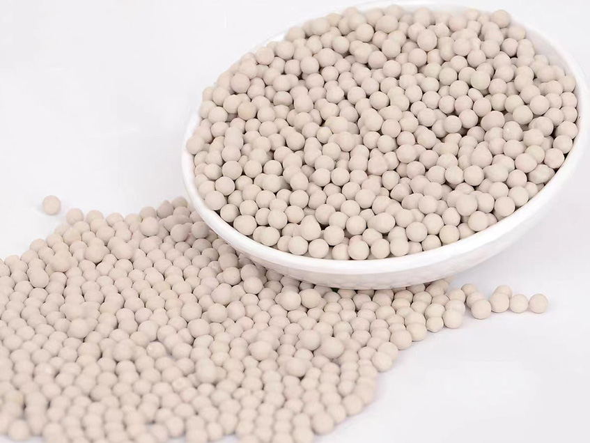
• How to Choose Carbon Molecular Sieve by Pore Size 0.3nm / 0.4nm / 0.5nm?

    When selecting carbon molecular sieves (CMS), pore size is the core factor determining nitrogen purity and application suitability.


    1.What Pore Size Actually Does: "Sieving" Gas Molecules by Size

    Carbon molecular sieves work by selectively adsorbing impurities. Under pressure, smaller molecules like oxygen (kinetic diameter: 0.346nm) diffuse faster into the micropores and are adsorbed, while nitrogen (0.364nm) diffuses more slowly and remains in the gas phase, ultimately collected as product gas. An unsuitable pore size will either fail to reach the required purity or reduce the gas production rate.


    2.Applications of 3 Common Pore Sizes


    Pore Size

    Core Function

    Suitable Nitrogen Purity

    Common Scenarios

    0.3nm

    Separates very small molecules like hydrogen and helium

    -

    Separate tiny molecules such as hydrogen and helium

    0.4nm

    Efficiently adsorbs oxygen and CO₂

    99.5%-99.9%

    Laser cutting, metal heat treatment, general industrial nitrogen generation

    0.5nm

    Low-purity nitrogen generation

    95%-98%

    High-flow, lower-purity applications where production rate is prioritized over purity


    3. Two Common Selection Mistakes to Avoid

    (1)Larger pore size is not always better: 0.5nm sieves also adsorb nitrogen, which reduces production rate and increases overall costs.

    (2)Do not arbitrarily change pore size in standard nitrogen generators: Different pore sizes require matching pressure and cycle parameters; random changes will cause system performance imbalance.


  • Powdering of carbon molecular sieve

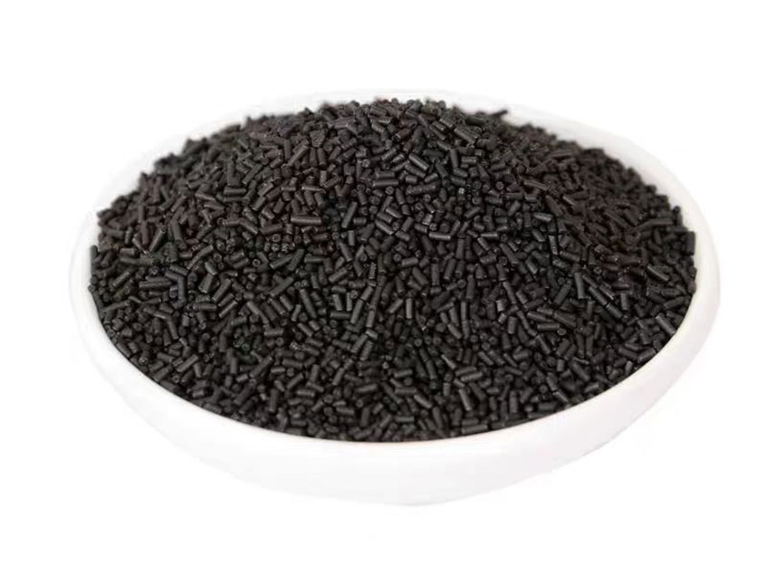
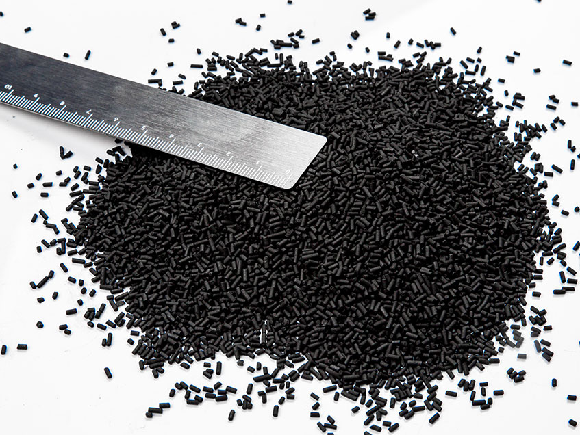
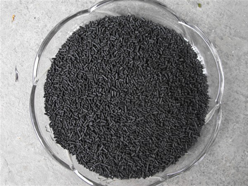
    Powdering  of Carbon Molecular Sieve (CMS) refers to the phenomenon where its particles crack and spall to form fine powder during use, transportation or storage. It is a critical issue that impairs the service life, adsorption performance and equipment operation stability of CMS, commonly occurring in the Pressure Swing Adsorption (PSA) process for nitrogen/oxygen generation.

    Carbon Molecular Sieve

    I. Main Causes of Powdering

    1. Mechanical Stress

    • Impacts during Loading, Transportation and Storage: High-altitude dropping during loading and severe jolting in transportation cause collision and extrusion between CMS particles, resulting in surface damage or internal cracks. These cracks expand to form fine powder in subsequent use.
    • Bed Pressure Difference Fluctuation: Rapid pressure switching during adsorption and desorption in the PSA process leads to repeated expansion and contraction of the CMS bed, intensifying friction between particles and causing atrophy after long-term cycles. Excessively high gas flow velocity will also generate cavitation effects, scouring the particle surfaces.
    • Equipment Vibration: Sustained vibration of the adsorption tower itself and auxiliary equipment is transmitted to the CMS bed, accelerating particle wear.


    2. Improper Operating Conditions

    • Abrupt Temperature Change: CMS has limited thermal stability. Excessively high heating temperature (above 200℃) during regeneration, or abrupt temperature rise and drop inside the adsorption tower, will cause uneven thermal stress inside CMS and trigger lattice fracture.
    • Influence of Moisture and Impurities: Excessive moisture in the feed gas causes CMS to absorb moisture, leading to the expansion of pore structure and damage to particle integrity. Moisture can also react with impurities to form corrosive substances that erode the CMS surface. In addition, oil contamination, dust and other impurities in the feed gas will block the CMS pores, causing local overheating or pressure concentration and indirectly exacerbating atrophy.
    • Adsorbent Saturated Overload: Failure to desorb CMS in a timely manner after it reaches adsorption saturation will cause the accumulation of adsorbate molecules in the pores to generate internal pressure, which cracks the particles.


    3. Inherent Quality Defects of the Product

    • Inadequate Forming Process: Insufficient addition of binders, improper control of calcination temperature or time during production will result in low mechanical strength of CMS particles with poor compression and wear resistance.
    • Uneven Particle Size and Pore Distribution: Excessively large differences in particle size, or defective pore structures (such as concentrated micropores and wide pore size distribution), will reduce the structural stability of particles and make them prone to cracking under stress.


    II. Preventive and Resolving Measures for Atrophy

    1. Optimize Storage, Transportation and Loading Processes

    • Adopt shockproof packaging for transportation to avoid severe jolting; adopt fluidized loading or layered slow loading during filling, strictly prohibit high-altitude dropping, and perform compaction after loading to reduce bed porosity.
    • Lay stainless steel wire mesh and quartz sand cushion at the bottom of the adsorption tower before loading, and install a pressure net or elastic gland on the top to limit the expansion and contraction displacement of the bed.


    2. Strictly Control Operating Conditions

    • Stabilize the pressure switching rate of the PSA system to avoid abrupt pressure difference; control the feed gas flow velocity within the designed range to prevent cavitation scouring.
    • Control the regeneration temperature between 150℃ and 180℃ to avoid overheating; the feed gas must undergo pretreatment (cooling, dehydration, deoiling, dedusting) to ensure that the dew point of the gas entering the adsorption tower is below −40℃ and the oil content is less than 0.01 mg/m³.


    3. Select High-Quality Carbon Molecular Sieve

    • Prioritize products with high compressive strength (radial compressive strength ≥100 N per particle) and good wear resistance, and require suppliers to provide forming process and strength test reports.
    • Select an appropriate particle size (e.g., 3~5 mm columnar molecular sieve) according to operating conditions to reduce stress concentration caused by uneven particle size.


    4. Regular Maintenance and Monitoring

    • Regularly check the pressure difference of the adsorption tower, product gas purity and filter pressure difference. A rapid rise in filter pressure difference indicates intensified CMS atrophy, and the causes must be investigated in a timely manner.
    • Regularly perform screening and cleaning on the CMS bed to remove accumulated fine powder; replace part or all of the CMS in a timely manner if atrophy is severe.


    III. Treatment Plan after Powdering 

    In case of obvious powdering , take the following steps for treatment:

    1.Shut down the equipment for venting, open the manhole of the adsorption tower, and clean up fine powder and damaged particles in the bed.

    2.Check whether the pretreatment system (dryer, filter) is invalid, and repair or replace the invalid components.

    3.Supplement new CMS and reload and compact it to ensure a uniform bed.

    4.Adjust operating parameters (such as pressure switching time and regeneration temperature) to avoid inducing atrophy again.


    For more information, please visit www.carbon-cms.com.

  • SLUHP-100 Molecular Sieve The Optimal Choice for High-Purity Nitrogen Generation, Outperforming CMS330 in All Aspects

    carbon molecular sieve

    In the field of industrial nitrogen generation, the performance of carbon molecular sieves directly determines nitrogen purity, gas production efficiency and operating costs. As a commonly used model in the market, CMS330 has maintained a certain application share for a long time. However, with technological upgrades, Chizhou Shanli, a leading enterprise in China's carbon molecular sieve industry, has launched the SLUHP-100 carbon molecular sieve.


    Boasting superior separation performance, more stable quality and more cost-effective operation, this product has comprehensively outperformed CMS330. It not only surpasses the industry standards in the domestic market, but also ranks among the world's top-tier products, emerging as the preferred core material for upgrading Pressure Swing Adsorption (PSA) nitrogen generation systems.


    The core competitiveness of the SLUHP-100 carbon molecular sieve lies in its precise control over "high-efficiency separation and cost-effective operation", which is also the key to its superiority over CMS330. Relying on Chizhou Shanli's independently developed micropore regulation technology, the SLUHP-100 achieves precise pore size matching. This accurate "molecular sieving effect" enables oxygen molecules to rapidly diffuse into the micropores and be adsorbed, while nitrogen molecules are efficiently retained. Thus, 99.999% high-purity nitrogen can be produced in a single step via the PSA method.


    In contrast, CMS330 features a wide and imprecise micropore size distribution. It not only struggles to stably produce 99.999% high-purity nitrogen, but also experiences a significant decline in separation efficiency under low-pressure operating conditions, failing to meet the requirements of high-end industrial applications.


    Beyond its core advantage of ultra-high purity output, the SLUHP-100 outperforms CMS330 across all key performance metrics, specifically reflected in two aspects:

    1.Lower air-to-nitrogen ratio: Under the same adsorption pressure, the SLUHP-100 consumes less compressed air than CMS330, directly reducing the energy consumption and operating costs of nitrogen generators.

    2.Lower ash content: The ash content of the SLUHP-100 is far lower than that of CMS330, which can effectively reduce the risk of molecular sieve pulverization, avoid pipeline blockage, and ensure the long-term stable operation of the nitrogen generation system. On the contrary, CMS330 is prone to pulverization after long-term use, requiring frequent shutdowns for maintenance.


    If your enterprise is currently using CMS330 and facing issues such as insufficient nitrogen purity, high operating costs or frequent equipment failures, or if you plan to upgrade your nitrogen generation system, feel free to learn more about Chizhou Shanli's SLUHP-100 molecular sieve. Choose this high-quality core material that comprehensively outperforms traditional models to make your nitrogen generation system more efficient, stable and cost-effective, and safeguard your enterprise's production operations.


    For more information on carbon molecular sieves, please visit www.carbon-cms.com.

  • Storage of Carbon Molecular Sieve

    carbon molecular sieve


    The core structure of carbon molecular sieve (CMS) consists of densely packed micropore channels, which are critical for its oxygen adsorption and nitrogen separation capabilities. Due to this unique structure, CMS is inherently “delicate” and vulnerable to two major threats—moisture and oil contamination—making protection against them the top priority in storage.


    First, moisture.Carbon molecular sieve is highly hygroscopic. Even short‑term exposure to air will cause it to rapidly absorb water vapor, filling its micropores with water molecules much like a water‑saturated sponge can no longer absorb other substances. Such damage is mostly irreversible, directly reducing the adsorption capacity of CMS by 30% to 50%, and in severe cases, rendering it completely unusable.This risk is especially high during the rainy season in southern China or in high‑humidity coastal regions, where relative humidity often exceeds 80%. Without proper moisture protection, even unopened CMS can gradually lose performance during storage.


    Second, oil contamination, which is even more damaging than moisture.Once the micropores of CMS come into contact with oil or grease, they become blocked. Oil also forms a thin film over the particles, completely eliminating adsorption activity. This type of “poisoning” cannot be reversed by regeneration; the CMS must be fully replaced.Oil contamination can originate from leaked lubricants in storage areas, oil from operators’ hands, or even residual grease on packaging containers. Even trace amounts of oil can cause catastrophic damage to carbon molecular sieve.


    In addition, temperature control during storage is equally important.The ideal storage temperature is 5–40 °C.Temperatures above 40 °C accelerate structural aging and reduce adsorption performance.Temperatures below 2 °C may cause adsorbed moisture to freeze and expand, damaging the micropore structure and even breaking the particles.


    In short, the key to preserving CMS is simple:maintain a dry, clean, and constant‑temperature environment, and isolate it from moisture and oil.This will maximize its original adsorption performance.


    If you want to get more information about us,you can click www.carbon-cms.com.
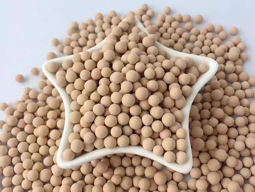


  • Technical Upgrade & Future Application Trends of 5A Molecular Sieve

    5A molecular sieve


    I. Technical Upgrade of 5A Molecular Sieve: From Basic Grade to High-Performance Grade

    1. Upgrade of Crystallization Process: Improved Pore Uniformity and Adsorption Capacity

    Traditional 5A molecular sieve is produced by conventional hydrothermal synthesis, which often leads to irregular pore channels and non-uniform crystal grain sizes, thus impairing adsorption performance. At present, the industry adopts the seed-directed synthesis method. By adding specific crystal seeds, the crystal size and pore structure of the molecular sieve can be precisely controlled, resulting in more regular pores and more accurate pore diameters.

    The adsorption capacity is increased by 10%–20%, and the regeneration energy consumption is reduced by approximately 15%.

    In addition, the application of advanced hydrothermal technologies (such as microwave-assisted synthesis and ultrasonic-assisted synthesis) shortens the crystallization time, lowers energy consumption and pollutant emissions during synthesis, and realizes green synthesis.


    2. Upgrade of Modification Technology: Enhanced Selectivity and Stability

    Performance optimization of 5A molecular sieve is achieved through modification technologies including ion exchange and metal loading, making it suitable for more high-end applications:

    • Loading metals such as palladium and platinum improves the hydrogen adsorption selectivity of 5A molecular sieve, enabling its use in high-purity hydrogen production (purity ≥ 99.999%).
    • Rare earth ion exchange enhances thermal stability and anti-poisoning capacity, prolonging service life for purification of highly impure gas streams.
    • Composite modification (e.g., combining with carbon materials or activated alumina) realizes the integration of adsorption and catalysis, which can be applied in waste gas treatment, fine chemical engineering, and other fields.


    3. Upgrade of Forming Technology: Adaptation to Diverse Industrial Scenarios

    Conventional 5A molecular sieve is mostly in powder form, which is prone to loss and equipment blockage in industrial applications. With continuous upgrading of forming technologies, 5A molecular sieve can be manufactured into spheres, strips, honeycombs, and other shapes.

    Among them, spherical molecular sieve (1–3 mm) is the most widely used, featuring good fluidity, uniform packing, low risk of clogging, large contact area, and high adsorption efficiency.

    Honeycomb-structured molecular sieve is suitable for waste gas treatment and large-scale air separation plants, enabling higher gas processing capacity.


    II. Future Application Trends of 5A Molecular Sieve: Focusing on Green and High-End Fields

    1. Hydrogen Energy: Supporting High-Purity Hydrogen Production and Storage

    As a clean energy source, hydrogen is central to the future energy transition. The production and storage of high-purity hydrogen (purity ≥ 99.999%) rely heavily on 5A molecular sieve.Upgraded 5A molecular sieve can efficiently remove trace impurities such as CO, CO₂, and water from hydrogen, and also enable adsorptive hydrogen storage, supporting large-scale applications of hydrogen energy.It will play a key role in both fuel-cell hydrogen and industrial hydrogen production.


    2. Environmental Protection: Waste Gas Treatment and CO₂ Capture

    With increasingly stringent environmental requirements, the demand for industrial waste gas treatment (e.g., vehicle exhaust, chemical waste gas) is growing rapidly.Modified 5A molecular sieve can act as a catalyst support for waste gas treatment, efficiently adsorbing and catalytically decomposing harmful components such as NOₓ and VOCs.It can also be used for CO₂ capture from industrial flue gas, helping achieve the “dual carbon” goals. Its application in the environmental field will continue to expand.


    3. Fine Chemical Industry: Precise Separation and Catalysis

    The fine chemical industry demands extremely high product purity, requiring precise molecular separation technologies.With its uniform pore size and modifiable properties, 5A molecular sieve is used for molecular separation (e.g., amino acid separation, perfume purification) and catalytic reactions (e.g., isomerization, alkylation), improving product purity and reaction efficiency and driving the upgrading of the fine chemical industry.


    If you want to get more information about us, you can click www.carbon-cms.com.

  • Types and Classification of Activated Alumina Catalysts in Exhaust Gas Treatment

    activated alumina


    There are many types of activated alumina catalysts used in exhaust gas treatment, with various classification methods. They can be broadly categorized into acid-base catalysts, metal catalysts, semiconductor catalysts, and zeolite catalysts. Their common characteristic is that they can exert varying degrees of chemisorption on reactants. Therefore, catalysis is inseparable from adsorption, and the general catalytic process starts with adsorption.


    Acid-Base Catalysts

    The acids and bases mentioned here refer to acids and bases in a broad sense, namely Lewis acids and Lewis bases. Both can provide acid-base active adsorption sites for the chemisorption of reactants, thereby promoting chemical reactions.Examples include activated clay, aluminum silicate, aluminum oxide, and oxides of some metals, especially oxides or salts of transition metals.


    Metal Catalysts

    The adsorption capacity of metals depends on the metal itself, the molecular structure of the gas, and adsorption conditions. Experiments have shown that metallic elements with empty d-electron orbitals exhibit different chemisorption capacities for certain representative gases.Except for calcium (Ca), strontium (Sr), and barium (Ba), most of these metals are transition metals. They form adsorption bonds with adsorbate molecules through electrons or free electrons that do not participate in the hybrid orbitals of metallic bonds, thereby catalyzing reactions between reactants.


    Semiconductor Catalysts

    These are mainly semiconductor-type transition metal oxides, divided into n-type semiconductors and p-type semiconductors, which provide quasi-free electrons and quasi-free holes respectively.N-type semiconductor catalysts form adsorption bonds with reactants via their quasi-free electrons, while p-type semiconductor catalysts rely on quasi-free holes. The formation of adsorption bonds changes the conductivity of the semiconductor, which is one of the main factors affecting catalyst activity.

    In fact, the formation of adsorption bonds between gas molecules and semiconductor catalysts is a very complex process. Studies on the catalytic mechanism of semiconductors have also found that energy bands generated by electron transitions play an important role in the formation of adsorption bonds. Therefore, it cannot be simply assumed that reactant molecules capable of donating electrons can only form adsorption bonds with p-type semiconductor catalysts.


    Zeolite Molecular Sieve Catalysts

    As adsorbents, zeolite molecular sieves  are widely used in drying, purification, separation and other processes. They began to emerge in the field of catalysts and catalyst supports in the 1960s.Zeolite refers to natural crystalline aluminosilicates with uniform micropore diameters, hence also known as molecular sieves. Hundreds of types have been developed so far, and many important industrial catalytic reactions rely on zeolite catalysts.

    The catalytic action of zeolites also depends on surface acidic sites to form adsorption bonds. However, they have higher selectivity than ordinary acid-base catalysts, as they can exclude molecules larger than their pore size from entering the internal surface. Meanwhile, the acidity and alkalinity on the zeolite surface can be artificially adjusted by ion exchange, giving them better performance than conventional acid-base catalysts.

    In recent years, a class of non-silicoaluminate synthetic molecular sieves has been developed and widely used in the field of catalysis. This shows that zeolites hold a unique position and play an irreplaceable role in catalysis.


    Any interestes or questions ,welcome to visit us at www.carbon-cms.com.

  • Which is better, a CNC machine or a laser engraver?

    Which is better, a CNC machine or a laser engraver?

    If you are in the manufacturing, signage, woodworking, or custom gifting business, this is the million-dollar question I hear every single week from buyers overseas.

    And my honest answer? Neither is "better." They are just different tools for different jobs.

    But since you are here to make a purchasing decision, let me break this down the way I explain it to my international clients—practical, cost-driven, and results-focused.

    The Short Version (For the Busy Importer)

    • Choose a CNC router if you work with thick materials, need 3D carving, or cut metals.

    • Choose a laser engraver if you prioritize ultra-fine detail, speed on flat surfaces, and work mainly with wood, acrylic, leather, or coated metals.

    Still with me? Good. Let’s dive deeper.

    1. What Each Machine Actually Does

    A CNC (Computer Numerical Control) router is a subtractive manufacturing workhorse. It uses a rotating spinning bit (end mill) to physically cut, carve, drill, and shape materials. Think of it as a robotic chisel.

    A laser engraver uses a focused beam of light to vaporize or burn away material. It does not touch the workpiece. It engraves, cuts thin sheets, and marks surfaces with incredible precision—like a high-speed light pencil.

    2. The Real-World Decision Matrix (For Your Factory Floor)

    Choose CNC if:

    • You produce furniture parts, cabinet doors, or moldings.

    • You cut solid wood, MDF, aluminum composite panels, or engineering plastics.

    • You need pockets, dovetails, or drilled holes—not just surface work.

    • You are okay with chip extraction systems and occasional bit changes (every 2–8 hours of cutting).


    Choose Laser if:

    • You run a promotional gifts factory (custom keychains, phone cases, wooden plaques).

    • You need to engrave barcodes, serial numbers, or QR codes onto products.

    • You cut acrylic displays, leather patches, or fabric layers.

    • You value production speed—a 50W CO₂ laser can cut 3mm plywood at 30mm/s, while a CNC takes 5x longer on the same job.

    3. Which One Is Easier to Operate?

    For beginners, the laser wins hands down. Software like LightBurn is intuitive. You load a file, set power/speed, and press start. Few mechanical failures.

    The CNC requires a steeper learning curve—feed rates, spindle RPM, stepover, climb vs. conventional milling, tool offsets. One wrong parameter can snap a $30 bit or ruin a $200 workpiece.

    4. The Final Verdict

    Do not ask, "Which is better?"
    Ask, "Which fits my order volume, material mix, and target market?"

    If you export to the US or Europe, your clients care about:

    Consistency (CNC wins for structural parts)

    Aesthetics (Laser wins for decoration)

    Lead time (Laser wins for thin materials)

    Durability (CNC wins for thick assemblies)

      •  

    Your Next Step

    Still undecided? Send me a message with:

    Your top 3 materials

    Your max workpiece size

    Your monthly output target

    I will reply within 24 hours with a tailored comparison chart and cost-per-part analysis—no fluff, just numbers.

    WhatsApp:'+86 15358102610

    📧 Email: zhouni@jsmdzn.com

    🌐 Website:https://www.mdzncnc.com/ 

  • How Surface Roughness Control Improves Stainless Steel Part Performance in Industrial Systems

    Introduction

    In industrial stainless steel components, most performance failures do not come from material strength alone—but from surface condition. Even when a part is machined to correct dimensions, poor surface roughness can lead to leakage, friction loss, contamination risks, or early corrosion.


    This is especially critical in systems such as chemical pipelines, fluid manifolds, pump housings, and food-grade processing equipment, where stainless steel parts operate under pressure, flow, or hygiene-sensitive environments.


    Surface roughness (Ra value) is one of the most important but often underestimated engineering parameters in CNC machining. Controlling it precisely is not just a finishing step—it directly determines sealing performance, service life, and system reliability.


    What Surface Roughness Actually Means in Machined Parts

    Surface roughness refers to the microscopic irregularities on a machined surface after cutting, turning, milling, or grinding. Even if a surface looks smooth to the naked eye, it may still contain peaks and valleys at a microscopic level.


    In stainless steel machining, typical Ra values include:

    • Ra 3.2 μm → general structural parts
    • Ra 1.6 μm → standard industrial components
    • Ra 0.8 μm → sealing or precision contact surfaces
    • Ra 0.4 μm or lower → high-end fluid or hygiene systems


    The lower the Ra value, the smoother the surface and the tighter the contact between mating parts.


    Why Surface Roughness Matters in Industrial Applications

    Surface roughness directly affects how stainless steel parts behave in real operating environments. The impact is not theoretical—it is mechanical, chemical, and operational.


    In sealing systems, such as flanges or valve seats, high surface roughness creates micro-gaps that allow fluid leakage under pressure. Even small imperfections can become leakage paths when pressure increases or thermal expansion occurs.


    In fluid systems, rough internal surfaces increase turbulence. This leads to pressure loss, reduced flow efficiency, and in some cases, particle buildup in industrial pipelines.


    In corrosion-sensitive environments, rough surfaces trap moisture and chemical residues more easily. These trapped elements accelerate localized corrosion, especially in chloride-rich environments such as marine or chemical processing systems.


    In mechanical assemblies, poor surface finish increases friction between moving parts. This leads to higher wear rates, increased heat generation, and reduced component lifespan.


    CNC Machining Strategies for Surface Roughness Control

    Achieving consistent surface roughness in stainless steel machining requires more than just a finishing pass. It depends on a combination of machining strategy, tooling selection, and process stability.


    One key factor is cutting tool geometry. Sharp carbide tools with optimized rake angles reduce tearing and deformation of stainless steel during cutting. This is especially important for materials like 304 and 316L, which tend to work-harden during machining.


    Another factor is cutting speed control. If cutting speed is too low, the material may deform instead of being cleanly sheared. If too high, heat buildup can degrade surface quality. Stable, optimized cutting parameters are essential for consistent Ra values.


    Tool path strategy also plays a major role. Continuous tool paths with minimal abrupt direction changes help maintain uniform cutting forces. This reduces surface vibration marks and improves finish consistency across the entire part.


    Coolant application is equally important. Proper high-pressure coolant not only reduces temperature but also flushes away chips that could scratch the surface during machining.


    Sealing Surface Requirements in Stainless Steel Components

    One of the most critical applications of surface roughness control is sealing surfaces. These include flange faces, valve seats, pump housings, and hydraulic connectors.


    For sealing applications, surface roughness must be carefully matched to gasket material and operating pressure.


    For example:

    • Soft gasket systems often require Ra 1.6–3.2 μm
    • Metal-to-metal sealing may require Ra 0.8 μm or lower
    • High-pressure chemical systems demand extremely stable flatness combined with low Ra values


    If surface roughness is too high, sealing failure may occur even if dimensional tolerances are correct. This is one of the most common hidden causes of leakage in industrial piping systems.


    Internal Surface Roughness in Fluid Systems

    Internal surfaces are often more difficult to control than external surfaces, especially in drilled or milled flow channels.


    In stainless steel manifolds, pump bodies, and distribution blocks, internal surface roughness affects flow efficiency and system stability.


    Rough internal walls create turbulence zones that increase pressure drop across the system. This forces pumps to work harder, increasing energy consumption and operational costs.


    In chemical systems, rough internal surfaces can also cause material buildup. Over time, this buildup reduces effective flow area and can lead to partial blockage or inconsistent dosing performance.


    For this reason, industries such as food processing, pharmaceuticals, and chemical dosing often require electropolished internal surfaces to achieve ultra-low roughness and high cleanliness standards.


    Case Insight: Surface Roughness Optimization in Pump Components

    In a recent industrial pump housing project, Shengtao Metal worked with a customer producing high-pressure fluid transfer systems for chemical processing applications.


    The initial design required Ra 1.6 μm on sealing surfaces and Ra 3.2 μm on internal non-critical surfaces. However, during engineering review, several improvements were introduced.


    By adjusting CNC finishing parameters and refining tool selection, the team achieved:

    • Stable Ra 0.8 μm on sealing interfaces
    • Improved flatness consistency across mating surfaces
    • Reduced post-machining polishing requirements
    • Lower rejection rate during pressure testing


    After implementation, the customer reported a significant reduction in leakage-related rework during final assembly and testing stages.


    This directly improved assembly efficiency and reduced production delays.


    Relationship Between Surface Roughness and Cost Efficiency

    Although achieving lower surface roughness often requires additional machining time, it can actually reduce total production cost when properly optimized.


    A well-controlled surface finish reduces:

    • Rework and polishing labor
    • Assembly leakage failures
    • Warranty and maintenance issues
    • Energy loss in fluid systems
    • Downtime caused by component mismatch


    In many industrial projects, improving surface quality early in machining eliminates much higher downstream costs later in assembly or operation.


    This is why surface roughness is not just a machining parameter—it is a system-level cost factor.


    Conclusion

    Surface roughness control is one of the most important technical factors in stainless steel machining, directly influencing sealing performance, fluid efficiency, corrosion resistance, and mechanical durability.


    Through optimized CNC machining strategies, proper tooling selection, controlled cutting parameters, and advanced finishing processes, manufacturers can achieve stable and precise Ra values tailored to different industrial applications.


    For industrial buyers, understanding surface roughness is essential not only for technical performance but also for long-term cost control and system reliability. A well-controlled surface finish reduces operational risks, improves assembly success rates, and enhances overall system efficiency.


    In modern stainless steel manufacturing, precision is no longer defined only by dimensions—it is equally defined by surface quality.


    Contact Shengtao Metal for Steel Product Solutions

    If you are looking for reliable steel and metal product solutions, feel free to send us your inquiry.

    Simply provide your specifications such as material grade, dimensions, quantity or application, and our team will respond quickly with professional support and a competitive quotation.

    Email: stsalesman4@stmetal001.com

  • Machining Thin-Wall Stainless Steel Components Without Deformation

    Introduction

    Thin-wall stainless steel components are widely used across modern industrial sectors, including instrumentation, fluid control systems, medical equipment, automation devices, food processing machinery, and semiconductor manufacturing. These components often require high dimensional accuracy while maintaining lightweight structures and complex geometries.


    Despite their advantages, thin-wall stainless steel parts present some of the most challenging machining conditions in CNC manufacturing. Unlike thicker structural components, thin-wall parts are highly susceptible to deformation during machining. Even minor cutting forces, clamping pressure, or thermal expansion can lead to dimensional inaccuracies that make components unusable.


    For manufacturers and equipment designers, controlling deformation is essential for achieving reliable product performance and reducing production costs. Understanding the factors that contribute to deformation and implementing effective machining strategies can significantly improve quality consistency and manufacturing efficiency.


    Why Thin-Wall Components Are Difficult to Machine

    The primary challenge of thin-wall machining is insufficient rigidity.


    As wall thickness decreases, the structural strength of the workpiece becomes significantly lower. During machining, cutting forces generated by milling, turning, or drilling operations can cause the material to deflect away from the cutting tool.


    Unlike solid components that can resist these forces, thin-wall structures behave more like flexible surfaces. Even a slight movement during machining can result in dimensional errors, uneven wall thickness, poor surface finish, or excessive vibration.


    Stainless steel compounds these challenges due to its material characteristics. Grades such as 304 and 316 stainless steel exhibit strong work-hardening tendencies. As the cutting tool engages the material, localized hardening can increase cutting resistance, generating additional stress on already fragile thin-wall structures.


    Thermal expansion is another concern. Stainless steel retains heat more readily than some other engineering metals. During prolonged machining operations, localized temperature increases can cause temporary distortion, making dimensional control more difficult.


    Common Deformation Problems in Thin-Wall Stainless Steel Parts

    Manufacturers frequently encounter several types of deformation when machining thin-wall components.


    Wall bending is one of the most common issues. This occurs when cutting forces push unsupported walls away from the tool path, resulting in dimensional deviations after the part is released from fixturing.


    Spring-back deformation can occur after machining is completed. Internal stresses generated during material removal may cause the part to change shape once clamping forces are removed.


    Ovality is often observed in thin-wall cylindrical components such as sleeves, bushings, and instrument housings. Improper chuck pressure during turning operations can distort circular features into slightly elliptical shapes.


    Surface chatter is another common issue. Thin walls are more prone to vibration during cutting, which creates visible tool marks and inconsistent surface finishes.


    In severe cases, deformation may render the component unsuitable for assembly, resulting in costly scrap or rework.


    Optimizing Material Removal Strategy

    One of the most effective ways to reduce deformation is through strategic material removal planning.


    Instead of removing large amounts of material from one side of a component, balanced machining strategies should be used whenever possible. Symmetrical material removal helps distribute internal stresses more evenly throughout the workpiece.


    Rough machining and finish machining should also be separated into distinct operations. During roughing, the goal is efficient material removal while leaving sufficient stock for finishing. Allowing the part to stabilize before final machining can reduce residual stress effects.


    For complex components, intermediate stress-relief processes may be introduced between machining stages. This is particularly useful for precision parts requiring extremely tight tolerances.


    Modern CAM software allows engineers to simulate material removal sequences and identify potential deformation risks before production begins.


    Importance of Proper Fixturing

    Fixturing plays a critical role in thin-wall machining success.


    Excessive clamping pressure can deform the workpiece before machining even begins. Once the component is released from the fixture, dimensional changes become immediately apparent.


    To minimize this risk, custom fixtures are often designed to distribute clamping loads across larger surface areas. Soft jaws, vacuum fixtures, and dedicated support structures can help stabilize thin-wall components without introducing excessive stress.


    For cylindrical parts, expanding mandrels are frequently preferred over traditional chucks because they provide more uniform support throughout the internal diameter.


    In some applications, temporary support ribs may be left in place during machining and removed during final finishing operations. This approach increases rigidity while critical features are being machined.


    Cutting Parameter Optimization

    Cutting parameters have a direct influence on deformation levels.


    Aggressive feed rates and excessive depth of cut increase cutting forces, making thin-wall structures more likely to deflect. Although reducing cutting forces may slightly increase cycle time, the improvement in dimensional accuracy often justifies the adjustment.


    Tool sharpness is equally important. Dull cutting tools generate more heat and require higher cutting forces. Maintaining proper tool condition helps ensure smooth material removal and reduces stress on the workpiece.


    High-speed machining strategies are frequently used for thin-wall stainless steel components because they allow smaller cutting engagements while maintaining productive material removal rates.


    Consistent chip evacuation also contributes to stability. Accumulated chips can interfere with cutting operations and cause surface damage or dimensional variation.


    Managing Heat Generation

    Thermal control is essential when machining thin-wall stainless steel parts.


    Heat generated during cutting can temporarily distort thin sections, affecting dimensional accuracy. Once the component cools, dimensions may change again, creating measurement inconsistencies.


    Modern machining centers utilize high-pressure coolant systems to maintain stable cutting temperatures. Coolant not only reduces heat but also improves tool life and chip evacuation efficiency.


    For critical tolerance applications, manufacturers may monitor workpiece temperature throughout the machining process. In some cases, finishing operations are performed after the component has returned to ambient temperature to ensure measurement accuracy.


    Maintaining thermal stability becomes increasingly important as wall thickness decreases and dimensional requirements become more demanding.


    Real Manufacturing Example

    A recent project at Shengtao Metal involved the production of precision 316L stainless steel sensor housings for process automation equipment.


    The component featured wall thicknesses ranging from 1.2 mm to 1.8 mm while maintaining strict dimensional requirements for sensor alignment and sealing performance.


    Initial production trials revealed minor wall distortion during internal boring operations. Engineering analysis identified a combination of excessive chuck pressure and aggressive finishing parameters as the primary causes.


    To address the issue, custom soft jaws were introduced along with revised machining sequences that balanced material removal more effectively. Cutting parameters were optimized, and additional support features were incorporated during intermediate machining stages.


    As a result, dimensional consistency improved by over 30%, while overall rejection rates were reduced significantly. The customer achieved stable assembly performance and reduced quality control costs during final equipment production.


    Long-Term Benefits of Deformation Control

    Successfully controlling deformation delivers benefits beyond dimensional accuracy.


    Higher machining consistency reduces scrap rates and minimizes rework requirements. Improved process stability leads to more predictable production schedules and lower manufacturing costs.


    Customers benefit from better component interchangeability, simplified assembly operations, and improved product reliability. In industries where precision and repeatability are critical, these advantages directly contribute to stronger operational performance.


    As industrial equipment becomes increasingly compact and sophisticated, demand for precision thin-wall stainless steel components will continue to grow. Manufacturers capable of controlling deformation effectively will be better positioned to support advanced engineering applications.


    Conclusion

    Machining thin-wall stainless steel components presents unique challenges that require specialized engineering knowledge and manufacturing expertise. Material characteristics, cutting forces, fixturing methods, heat generation, and machining strategies all play important roles in determining final part quality.


    By optimizing material removal processes, implementing proper fixturing solutions, controlling cutting parameters, and managing thermal effects, manufacturers can significantly reduce deformation risks and achieve consistent production results.


    For industrial buyers seeking high-precision stainless steel components, selecting a manufacturing partner with proven experience in thin-wall machining is essential for ensuring quality, reliability, and long-term project success.


    Contact Shengtao Metal for Steel Product Solutions

    If you are looking for reliable steel and metal product solutions, feel free to send us your inquiry.

    Simply provide your specifications such as material grade, dimensions, quantity or application, and our team will respond quickly with professional support and a competitive quotation.

    Email: stsalesman4@stmetal001.com

  • The Role of Tool Path Optimization in Reducing CNC Stainless Steel Machining Costs

    Introduction

    In CNC machining, most people focus on materials, machines, or cutting tools—but one of the most powerful cost drivers is often invisible: the tool path.


    Tool path refers to the exact movement route a CNC machine follows during cutting operations. For stainless steel components, where machining resistance is high and tool wear is significant, inefficient tool paths can dramatically increase cycle time, tool consumption, and overall production cost.


    Tool path optimization is therefore not just a programming improvement—it is a direct cost reduction strategy that impacts productivity, energy consumption, tool life, and final part quality.


    What Tool Path Optimization Really Means

    Tool path optimization is the process of refining CNC programming routes to ensure that every cutting movement is efficient, stable, and necessary.


    A poorly optimized tool path may include:

    • Excessive air cutting (non-cutting movement)
    • Unnecessary direction changes
    • Overlapping machining passes
    • Redundant tool re-entry points
    • Inefficient roughing and finishing separation


    In stainless steel machining, these inefficiencies become even more costly because the material is harder, tool wear is faster, and heat buildup is more severe.


    A well-optimized tool path reduces machining time while maintaining precision and surface quality.


    Why Stainless Steel Requires Special Tool Path Strategy

    Stainless steel is not a forgiving material. Its machining characteristics include work hardening, high cutting resistance, and heat retention. These properties make tool path strategy especially important.


    If the tool path is not optimized, the tool may repeatedly cut hardened material, increasing wear and reducing tool life. This leads to inconsistent dimensions and higher replacement costs.


    Heat concentration is another issue. Poor tool paths can trap heat in localized areas, causing thermal deformation of both the tool and workpiece. This directly affects dimensional accuracy.


    Chip evacuation is also critical. Stainless steel produces long, tough chips that can interfere with cutting if not properly managed through tool path design.


    For these reasons, tool path optimization is a core engineering requirement rather than a programming luxury.


    Roughing Strategy Optimization for Cost Reduction

    Roughing is the first stage of material removal and has the highest impact on cycle time. Optimizing roughing tool paths can significantly reduce machining cost.


    Modern strategies include adaptive clearing and high-efficiency milling paths that maintain constant tool engagement. This prevents sudden load spikes that damage tools or slow down machining.


    Instead of traditional straight-line passes, optimized roughing uses dynamic paths that adjust cutting depth and direction based on material resistance.


    This results in:

    • Faster material removal rates
    • Reduced tool stress
    • Lower energy consumption
    • More stable machining conditions


    In stainless steel machining, these improvements can reduce roughing time by 20–40% depending on part geometry.


    Finishing Path Optimization and Surface Stability

    Finishing operations require a different approach. While roughing focuses on speed, finishing focuses on stability and surface consistency.


    Optimized finishing tool paths minimize vibration and ensure consistent tool contact with the surface. This is especially important for stainless steel parts that require tight surface roughness control.


    Continuous contour paths are preferred over segmented or interrupted passes. This reduces tool marks and improves dimensional accuracy.


    Reducing tool retraction and re-entry points also helps maintain uniform surface finish, especially on sealing surfaces and precision mating features.


    Reducing Air Cutting and Idle Movement

    One of the biggest hidden costs in CNC machining is air cutting—tool movement without actual material removal.


    In poorly optimized programs, machines may spend a significant portion of cycle time moving between cutting zones unnecessarily.


    By optimizing tool entry points, sequencing operations intelligently, and minimizing unnecessary repositioning, air cutting time can be significantly reduced.


    For stainless steel parts with multiple features, this optimization alone can reduce total cycle time by 10–25%.


    Multi-Axis Tool Path Efficiency

    For complex stainless steel components such as manifolds, pump housings, and structural brackets, multi-axis CNC machining plays a major role in efficiency.


    However, without proper tool path planning, multi-axis machines can become inefficient due to excessive rotation, repositioning, or collision avoidance delays.


    Optimized multi-axis tool paths allow the tool to approach the workpiece at ideal angles, reducing the need for multiple setups. This improves both accuracy and production speed.


    It also reduces fixture complexity, which lowers overall production cost and improves repeatability across batches.


    Impact on Tool Life and Production Cost

    Tool path optimization directly affects tool wear. Stainless steel machining is already tool-intensive, and inefficient paths accelerate tool degradation.


    Stable tool engagement reduces sudden load changes, preventing chipping and premature failure of cutting inserts. This extends tool life and reduces tooling cost per part.


    In large production runs, even a small improvement in tool life can lead to significant cost savings.


    Additionally, fewer tool changes reduce machine downtime, increasing overall production efficiency.


    Case Insight: Cycle Time Reduction in Stainless Steel Flange Production

    In a stainless steel flange production project for an industrial fluid system manufacturer, Shengtao Metal implemented tool path optimization across CNC milling operations.


    The original machining program included multiple unnecessary tool retractions and inefficient roughing patterns.


    After optimization, improvements included:

    • Reduced air cutting by restructuring operation sequence
    • Applied adaptive roughing tool paths
    • Optimized finishing passes for sealing surfaces
    • Reduced tool change frequency through consolidated operations


    Results achieved:

    • Cycle time reduced by 28%
    • Tool wear reduced by 18%
    • Production consistency improved significantly
    • Per-unit machining cost reduced by 14%


    The customer was able to scale production without increasing machine capacity, directly improving profitability.


    Tool Path Optimization and Lean Manufacturing

    Tool path optimization is closely aligned with lean manufacturing principles. Both aim to eliminate waste—whether in time, motion, material, or energy.


    In CNC machining, waste is often hidden in inefficient motion. Optimizing tool paths removes this waste without requiring additional machines or labor.


    This makes it one of the most cost-effective improvements in stainless steel manufacturing, especially for high-volume production.


    Conclusion

    Tool path optimization is one of the most powerful but often overlooked factors in CNC stainless steel machining cost control.


    By reducing air cutting, improving roughing efficiency, stabilizing finishing passes, and enhancing multi-axis coordination, manufacturers can significantly reduce cycle time, extend tool life, and improve machining consistency.


    For industrial buyers, these improvements translate into lower per-unit cost, faster delivery, and more stable production quality.


    In modern CNC manufacturing, efficiency is no longer determined only by machines or tools—but by how intelligently those tools move.


    Contact Shengtao Metal for Steel Product Solutions

    If you are looking for reliable steel and metal product solutions, feel free to send us your inquiry.

    Simply provide your specifications such as material grade, dimensions, quantity or application, and our team will respond quickly with professional support and a competitive quotation.

    Email: stsalesman4@stmetal001.com